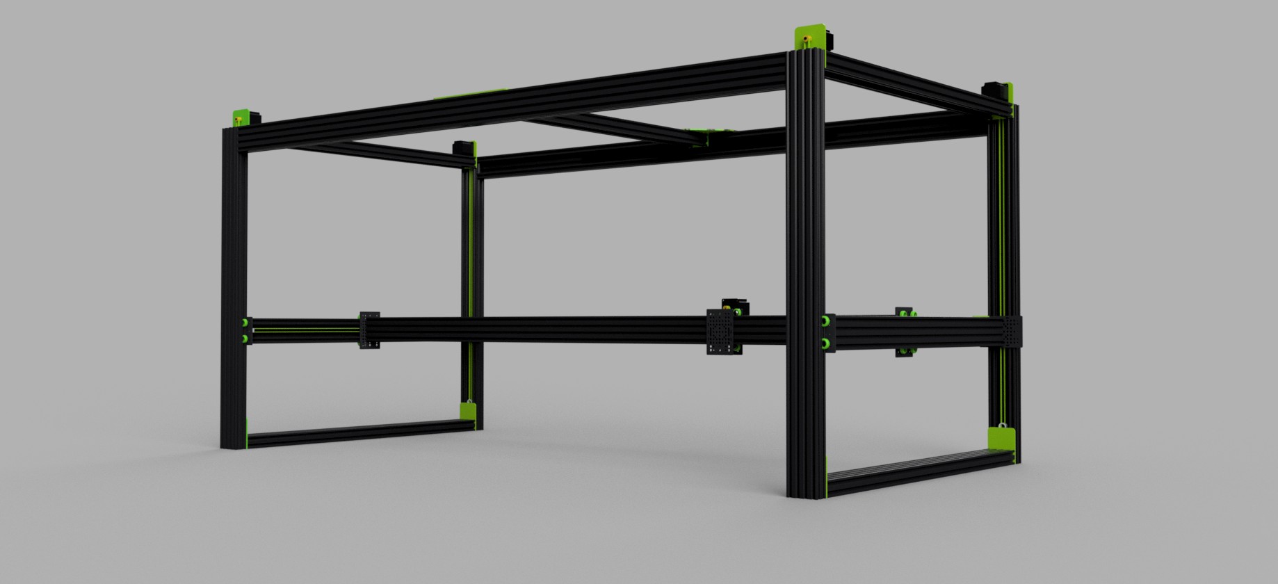
Historical development note: this page describes the April 2026 M3-2 CAD snapshot. It is not a current procurement list, complete construction package, or physical-validation record. The versioned STEP and source are published under the repository's stated licenses; verify the current files, BOM, exclusions, and evidence before use.
What the M3-2 Is
The M3-2 is the default experimental M3-CRETE configuration. Its source currently declares a 2000 × 1000 × 1000 mm design-envelope target. That target is not a verified working volume or exterior footprint. Travel, clearances, loads, accuracy, repeatability, print-material behavior, and suitability for any object or structural application require independent physical testing and qualified review.
The reference architecture assigns NEMA23 motors to one X, two Y, and four Z axes, with a BTT Kraken/TMC5160 control reference. The printhead interface target is 1-inch NPT and the modeled moving-mass target is approximately 1.5 kg. These configuration choices do not establish available torque, load capacity, safe training use, production suitability, or motion performance.
One Extrusion. One Length. One Bolt Kit.
The April reference moved the primary frame concept toward 40 × 80 C-beam in 1000 mm stock lengths, with separate reinforcement and hardware entries. The current BOM JSON—not this article—controls quantities, exclusions, and supplier references. Profile choice alone does not protect operators or equipment; guarding and risk controls remain separately engineered.
The current reference uses 1000 mm stock segments partly to constrain sourcing and shipping experiments. No carrier acceptance, parcel count, delivery time, surcharge status, assembled shipping method, or structural equivalence for alternate lengths is established here. Verify current carrier rules and perform a separate engineering review before changing member lengths or splice geometry.
This was a development choice intended to reduce primary-profile variation compared with an earlier mixed-profile concept. It does not eliminate separate reinforcement, hardware, fabricated-part, controls, or professional-scope requirements:
- Procurement hypothesis. Fewer primary-profile variants may simplify quoting, but the live BOM and fabrication scope still require line-by-line reconciliation.
- Structural hypothesis. Section geometry can affect stiffness, but the actual members, joints, spans, loads, deflection, fatigue, and safety factors require engineering analysis and physical evidence.
- Routing intent. The channel provides possible protected routing space; cable, belt, contamination, bend-radius, inspection, and service requirements still need design review.
- Tradeoff. Mass, cost, handling, joint behavior, and stiffness must be measured for the selected source and configuration rather than inferred from profile name alone.
The BOM retains dated supplier references for comparison. They are not endorsements or current claims of inventory, origin, exclusivity, price, delivery time, landed cost, compatibility, or support. Buyers must verify every listing and substitution directly before ordering.
The frame change affects mass, handling, shipping, joint loads, motion response, and cost. This article does not retain a controlled comparison sufficient to quantify those effects. Treat the choice as an experimental design decision pending measured evidence, not a settled performance conclusion.
One caveat up front: the 2000 mm X-axis span still requires splicing at center, regardless of stock length, two equal-length pieces reinforced with a 2040 sliding inside the C-beam channel. The win is uniformity, not the elimination of splices.
The Design Scope
Frame: the historical snapshot describes primary C-beam members, four Z-posts, Y rails, a top X-frame, a spliced X-axis gantry concept, and internal 2040 reinforcement. Current quantities and exclusions must be read from the BOM JSON. Alternate stock lengths and splice counts are not declared interchangeable without engineering review.
Motion: seven motors, 3D-printed spacer+motor brackets, GT2 10 mm belts, hub disks for the Z-axis, smooth idlers at the bottom of each Z-post, polycarbonate V-wheels with eccentric spacers for zero-backlash adjustment.
Gantry: eight plates total: four Z-corner plates, dual Y-gantry plates, and two X-carriage plates for the printhead. Earlier mixed-V-slot revisions used sandwich pairs at every corner. C-beam removed the corner sandwiching; the channel captures the wheels on one face, so a single plate per corner now does the work two used to in the older design.
Cable management: three drag chain assemblies, 2x Y and 1x X (the X-axis is dual-action, with two chains running in unison).
Electronics: a BTT Kraken with 8× TMC5160 drivers, a Raspberry Pi 5 running Klipper, a 7-inch touchscreen.
Pump system: intentionally excluded. M3-CRETE is the motion platform. The pump is a separate problem with separate constraints. We will address it separately.
Why CERN-OHL-W
M3-CRETE identifies covered hardware files under CERN-OHL-W-2.0. The license text—not this summary—governs copying, modification, manufacture, and distribution obligations. Review the exact covered files and license, and obtain legal advice for a commercial distribution or mixed-license integration.
The CAD source, BOM, assembly scripts, and component library are all in the GitHub repo. The STEP files are there for people who want to import and build. The Python source is there for people who want to modify, extend, or learn.
How It Was Built
The assembly workflow combines manually authored/imported component geometry with project scripts that classify selected shapes and substitute simplified parametric geometry. Those substitutions are intended to reduce unnecessary third-party detail, but they do not replace file-by-file provenance, attribution, license, and rights review.
The repository includes a STEP snapshot, Python source, and automated checks for selected declared rules such as dimensions, positions, alignments, spans, and clearances. A passing check only addresses encoded rules and does not establish geometry completeness, manufacturing tolerance, fit, structural performance, safety, or physical validation.
Build Log #2 covers this workflow (the hybrid Fusion-plus-CadQuery pattern, the invariant harness, and the AI-assisted development loop) in detail.
Get the Files
- Full STEP assembly:
CAD/M3-2_Assembly.step, 32 MB - Parametric source:
CAD/m3_2_assembly.py - Invariant harness (preview, with a deep dive in Log #2):
CAD/preview_assembly.py - Interactive BOM: bom.m3-crete.com/bom
- GitHub: github.com/sunnyday-technologies/M3-CRETE
Extrusions on order. Frame build films as soon as they land. Episode 1 of the YouTube build series covers the frame assembly.