The frame, the motion, the CAD — all of it has a published source of truth. The control box didn't. It lived as a pile of parts on a workbench and a few hand-drawn arrows. So we built a tool to plan it properly.
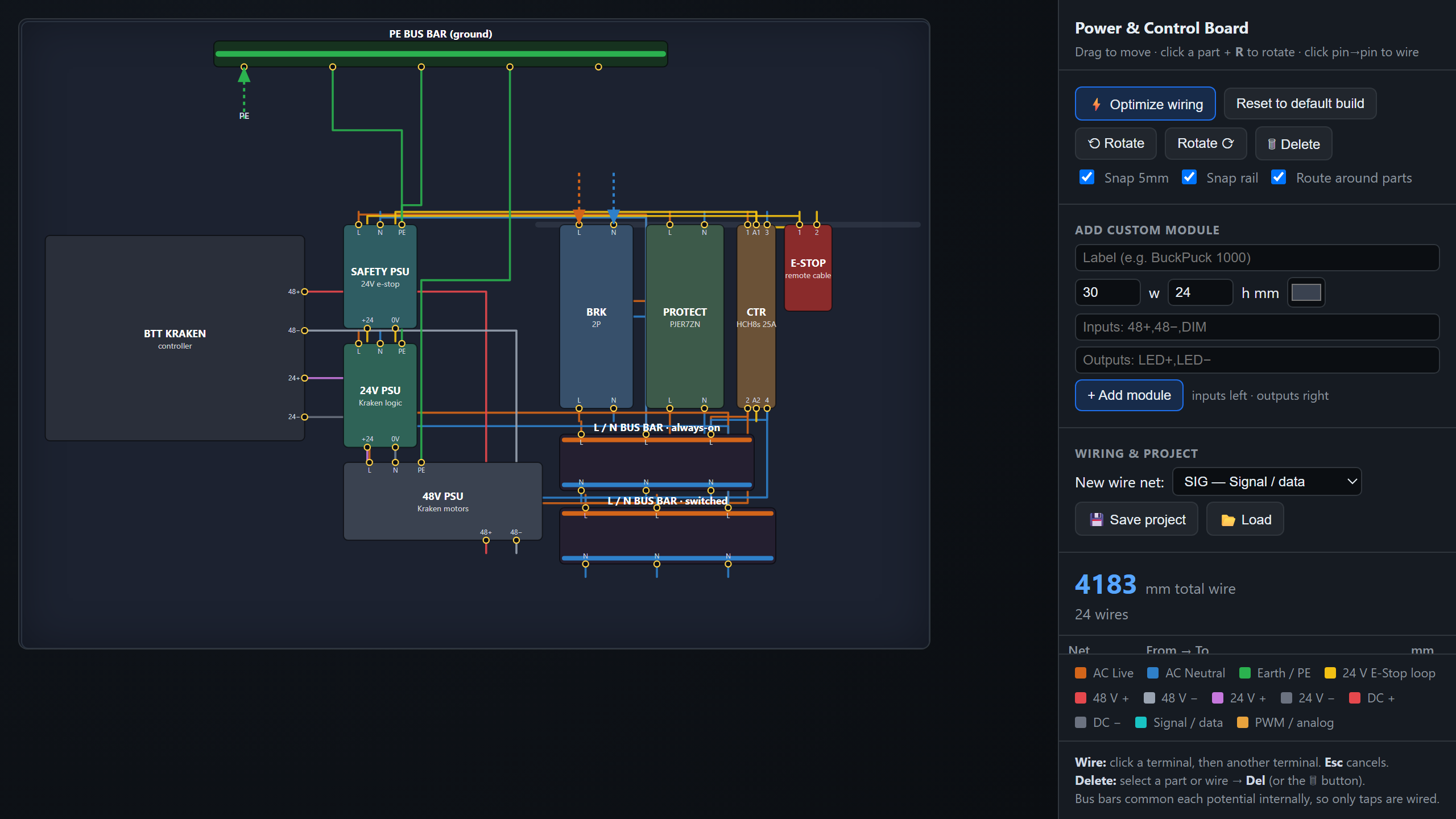
The Control Panel layout planner is now live. It's an interactive, to-scale drawing of the M3-CRETE power and control enclosure: breaker, intelligent protector, contactor, the three power supplies, DIN bus bars, and the BTT Kraken. Drag the parts around and the wiring re-routes itself, orthogonally, with a running total of wire length so you can see immediately whether a layout is tidy or a rat's nest.
Why a layout tool at all
Planning an enclosure by eye is the same trap as planning a 99-part CAD assembly by eye — it works until it doesn't. Where does the safety supply sit so the e-stop loop stays short? Which way do you turn a PSU so its DC terminals face the controller instead of the wall? Does the switched bus reach both machine supplies without crossing the whole panel? You can guess, or you can move the part and watch the number change.
So that's the core of it:
- Drag to move,
Rto rotate. Terminals rotate with the part — turning a bus bar on its end or flipping a supply is usually where the biggest wiring savings hide. - One-click optimize. A simulated-annealing pass slides and rotates parts to shrink total wire length while keeping DIN devices on the rail and off each other. Press it a few times, keep the best.
- Bus bars, done right. The ground and L/N distribution are modeled as DIN bus bars that common each potential internally, so you only wire the taps.
The part you asked for: bring your own modules
No two builds will share the exact same control box. People are bolting on LED BuckPucks, digital-to-analog converters, sensor boards, relays — things that aren't in the default M3-CRETE layout and never will be. So the tool lets you add them.
Open Add custom module, give it a label and an X-Y size in millimeters, and list its inputs and outputs. A BuckPuck becomes inputs 48+, 48−, DIM and outputs LED+, LED−; a DAC becomes VCC, GND, SIG-IN in and AOUT out. The pins drop onto the body — inputs on the left, outputs on the right — ready to wire. Click one terminal, then another, and you've drawn a connection. Save the whole layout (parts, positions, rotations, and the netlist) to a JSON file and load it back later, or hand it to someone else.
Where it's going
It's deliberately simple and self-contained — one page, no accounts, runs entirely in your browser. The default layout is the SN 001 control box as we're building it; fork it for yours. If there's a module type worth shipping as a built-in, or a feature that would make it more useful on a real bench, open an issue on GitHub.
The frame had a source of truth. The CAD had a testing harness. Now the control box has a planner.