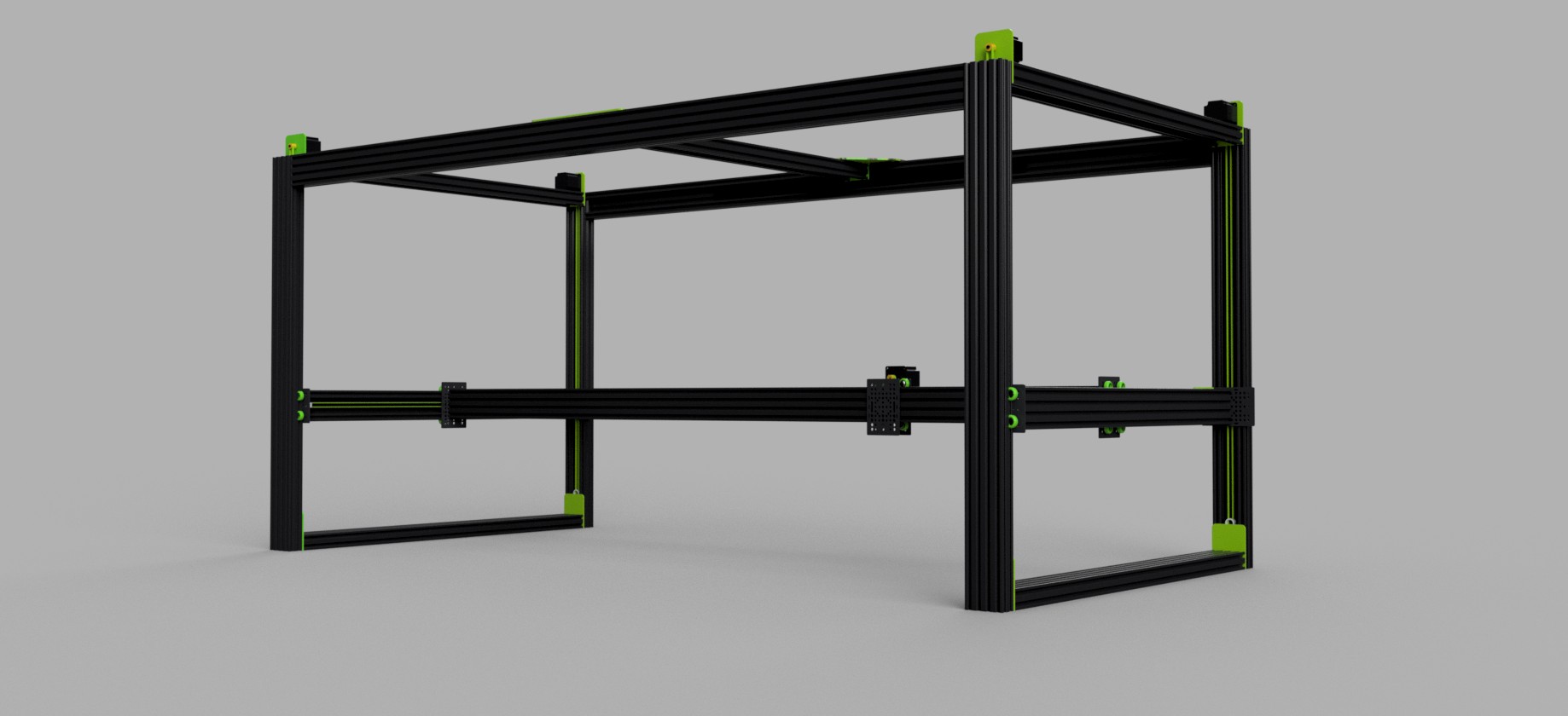
Historical development note: this article describes an earlier M3-CRETE assembly-checking experiment that later became CADCLAW. Early numbers in working notes were not retained here as a controlled claim-to-proof record, so this revision does not present them as current validated metrics.
The Problem
Visual review of a growing assembly missed intersections, misplaced components, and dimensional drift. Software checks helped surface selected geometry-rule failures that were difficult to spot at normal screen scale. A finding identifies a model condition for review; it does not by itself establish structural consequence or physical fit.
The project scripts became CADCLAW, an open-source framework for encoding and checking selected STEP-assembly rules alongside human review.
The Review Gap We Were Addressing
Software developers have had automated testing for decades. Write code, write tests, run CI. If something breaks, you know before it ships. Shipping code without tests is considered unprofessional.
Mechanical CAD review also depends on authored requirements, tolerances, analysis, manufacturing knowledge, inspection, and physical testing. Our immediate gap was narrower: we lacked repeatable automated checks for selected model conditions alongside visual inspection.
As the M3-CRETE development assembly grew, manual visual inspection alone became insufficiently repeatable. The current BOM and model—not the historical counts in this article—are the source for present configuration review.
Five Gates
Inventory. Configured bounding-box signatures can help classify expected model instances. Supplier variants and modeling simplifications can share or change dimensions, so signatures are heuristics tied to declared rules, not identity proof.
Interference. The check can run solid-solid boolean operations through OpenCascade and report modeled overlap volume. Results depend on geometry quality, tolerances, exclusions, and configuration, and still require engineering interpretation.
Adjacency. Declared distance rules can identify components that are unexpectedly far from or close to another modeled item.
Dimensional. Declared range checks can flag geometry whose measured bounding dimensions differ from encoded expectations.
Analysis inputs. Project scripts can evaluate simplified beam, belt, motor, or motion assumptions. Their outputs are sensitive to materials, joints, constraints, loads, boundary conditions, and model fidelity. They are screening calculations, not accepted structural analysis or measured machine performance. Earlier carbon-fiber concepts are not part of the current reference build.
What the Historical Run Demonstrated
- Automated checks can make selected geometry-rule regressions repeatable and reviewable.
- Simplified parametric replacements can reduce unnecessary imported-detail complexity, subject to provenance and fidelity review.
- Interference, adjacency, inventory, and dimensional findings can direct a human to model regions that need investigation.
- A passing run covers only encoded rules and never substitutes for manufacturing, tolerance, structural, safety, or physical validation.
Commercial Comparison Boundary
This project does not publish a controlled feature, price, labor, accuracy, support, or outcome comparison against commercial CAD suites or professional engineering services. CADCLAW is an open-source checking option, not a replacement claim.
The Human-AI Part
This framework was developed through human CAD work, scripted geometry processing, and AI-assisted code drafting. AI output and automated check output require human review; neither validates the assembly.
I catch things the AI can't — “that bracket needs to clear the belt path” requires physical intuition. The AI catches things I can't — “plate 17 overlaps C-beam 4 by 1,003 mm³ at coordinates (2102, 18, 20)” requires checking 4,800 part pairs in 3 seconds.
The harness is one evidence source in a larger review process. A pass means only that the evaluated model satisfied the encoded checks for that run; unencoded defects and real-world failure modes remain possible.
Try It
- CADCLAW: github.com/sunnyday-technologies/CADCLAW
- M3-CRETE printer: github.com/sunnyday-technologies/M3-CRETE
- Interactive BOM: bom.m3-crete.com/bom
See the current CADCLAW repository for its license, dependencies, tests, supported workflows, and known limitations; this dated article is not release documentation.
If you've ever spent an afternoon squinting at an assembly wondering if something's clipping — this exists now.